When I first got into electrical work through industrial automation, I found the process of wire sizing to be baffling. The National Electric Code (NEC / NFPA70) does contain the requirements, but isn’t much help teaching their application in specific situations. In the following post, I’ll give you the jist of what I’ve learned and what you’ll need to do basic residential wiring. At the end of the day, the ampacities (currents) involved in residential work are relatively small and you’ll see that greatly simplifies the process.
As usual, IANAGOSE (I am not the right kind of engineer), so hire a electrician licensed in your area if you need project-specific advice or help. Before you touch anything electrical in your house (1) ensure you know enough about what you’re doing to be safe – electricity is good at starting fires and (2) ensure that you, as a homeowner, are actually allowed to pull permits and do electrical work on your own home. Many states have strong restrictions in place (think Texas).
HELPFUL RESOURCES
Ultimately, you’ll need access to a code book. You can purchase one and receive a print copy, or view them for free online. The viewer, however, seems intentionally designed to frustrate you.
A better options for most people is to pick up a copy of Ugly’s Electrical Reference. Its inexpensive, small enough to fit in your tool bag, and contains excepts of only the most import tables and codes.
WIRE TYPE
Depending on where you live, the branch circuits in your house will either be Romex (called non-metallic or NM) or THHN in conduit. Most of the country uses NM; however, growing up in Chicago where conduit is a code requirement, I feel more comfortable working with conduit. If you use NM, you have to place protective metal plates over studs with wire in them. In practice, this step is often neglected and I frequently hear stories of people puncturing wires while hanging pictures.
Non-metallic (NM) is a flexible bundle of solid conductors with a plastic jacket. It is often color coded yellow or orange to signify the wire gauge. The benefit of NM is that it is quick to install and usually just has to be stapled in place.
The alterative is called building wire or THHN. THHN consists of individual solid or stranded conductors in a nylon jacket. The wires are pulled through a rigid conduit composed of either steel (EMT) or PVC. In the absence of a local code requirement, you have the choice of solid or stranded wire. While stranded is more flexible and therefore easier to pull through conduit, it presents issues when terminating a circuit at an outlet and requires special care. In general, solid will also be a smaller diameter wire for the same wire gauge.
Often a wire will have multiple listing / approvals. While at the hardware store, you may see a wire cross-listed as THHN, THHW, XHHN, MTW. Each approval has a specific application, but as long as your wire has the approval you need, it will work (e.g. THHN).
WIRE GAUGE
All wire, regardless of type, will have a listed wire gauge. The gauge of the wire (not your circuit breaker) ultimately determines the allowable ampacity (current) of the circuit. Small wire typically used in domestic branch circuits is measured in AWG with smaller number representing larger wire (6 AWG is much thicker than 12 AWG). Wires bigger than 0 AWG are typically referred with multiple zeros (i.e. #00 AWG) or a shorthand is used (i.e. #00 = 2/0, #0000 = 4/0). Again, 4/0 is bigger than 2/0. Once you get bigger than 4/0, wire is measured in thousands of circular mills (kcmil). You will typically only see 350 kcmil+ wire in service entrance conductors installed by your utility.
The outer jacket of NM wire is conveniently color coded to help you identify what gauge wire it contains: white is 14 AWG, yellow is 12 AWG, orange is 10 AWG, and black is anything thicker.
WIRE COLOR
Wire color is used by electricians to get an idea of what a given conductor does. It’s important to follow this convention, so that future individuals working on your house do not risk touching a hot wire when they think they are touching a ground. In general, the following color convention is used in residential work:
| WIRE COLOR | FUNCTION |
| BLACK | Hot / 120 VAC (Especially Phase A) |
| RED | Hot / -120 VAC (Especially Phase B), after a light switch, or as 3-way switch travelers. |
| WHITE / GREY | Only for neutral circuit (0 VAC) |
| GREEN / GREEN w/YELLOW | Only for ground conductors |
| ORANGE | You probably won’t see this color in a residential system, but if you do, watch out. It represents a higher voltage available in an older, rare, wiring system called high-leg delta. |
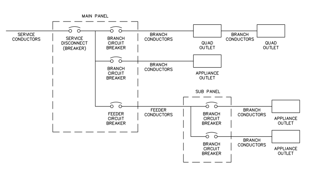
SERVICE, FEEDER, and BRANCH CIRCUITS
The NEC will constantly refer to a circuit being either a service, feeder, or branch circuit and have type specific tables for determining wire size. This was a key point of confusion for me for a while.
A branch circuit is simply the circuit downstream of the last circuit breaker (OCPD), anything else (besides the service) is a feeder.
You will typically encounter feeders between load panels, otherwise everything connected to a circuit breaker in your main load panel is a branch circuit. Feeders travel from circuit breaker to circuit breaker. The service is the line between the pole and your main load panel (usually interrupted by a meter).
SMALL CONVENIENCE OUTLETS
Outlet circuits are typically 14 AWG THHN / NM for 15 A outlets, or 12 AWG for 20 A outlets. There is no limit on the number of outlets you can connect to a circuit, but the wire gauge will limit what size circuit breaker you can put on the circuit. Typically you will run a black (hot), white (neutral), and green (ground) conductor all of the same size.
240V APPLIANCES
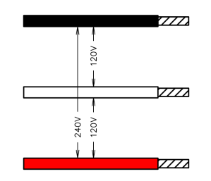
Larger appliances such as electric ranges, ovens, and dryers typically require 240V circuits. The load panel in your house contains two phases (A and B) that are essentially +120V and -120V. If you connect either phase and neutral to an outlet, you get a difference of 120V. If you connect each phase to an outlet, you get 240V between them. This setup is called 120/240V split-phase supply and is a common residential setup. The A Phase is typically signified by black wire, and the B Phase is typically a red wire; however, many electricians use black for both phases or really any color they want other than white, grey, or green. Some 240V appliance still required a white neutral wire because while they use 240V between black and red for the high power components (heaters), they use 120V between black and white for the user facing buttons and controls.
A NOTE ON NON-STANDARD OUTLETS (RECEPTACLES)
Outlets are actually design to prevent you from plugging something into them that you shouldn’t, so its important that you use the right outlet for your application.
THE BIG STUFF
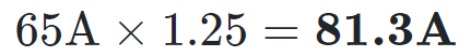
This is where you actually have to do the math. Let’s say we have an air compressor in our garage that takes a lot of power. If you look at the equipment nameplate, it says 65A @ 240 VAC. How do we choose a wire size? Well, the 240V only tells you that you need two phases to power it (red and black wire). The wire size is entirely dependent on the current draw of the device.
The first step is to multiple the current by 1.25x. You are only allowed to use up 80% of a circuits capacity continuously.
Now we can go to NEC Table 3.10.1.16 Allowable Ampacities for Insulated Conductors and find the column for (1) copper conductors and (2) 60°C temperature rating. You may notice that THHN falls under the 90°C category. Unfortunately, the circuit ampacity is limited by the temperature rating of the equipment (e.g. outlets, etc.) terminals—which is always 60°C. The 90°C column for THHN will be able to be used later if you need temperature and conduit fill correction factors.
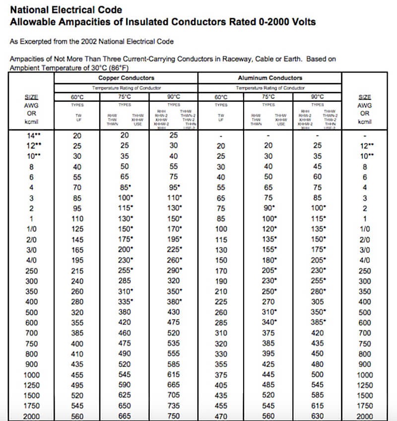
For our 81.3A load, we will need at least 3 AWG THHN. The circuit breaker in your panel is allowed to be the next larger common size (per NEC 240.6(A) those are 15, 20, 25, 30, 40, 45, 50, 60, 70, 80, 90, 100, 110, 125, 150, 175, and 200A). We’d need a 90A breaker.
NOTE: the table says for it only apply to not more than three current carrying conductors.
This isn’t a problem if you run an individual circuit (black, red, green — not current carrying) in the conduit to your air compressor, but if it shares a conduit with other loads, you’ll have to apply a correction factor to the wire.
Say there are 5 other current carrying conductors in that circuit, bringing the total to 7? Well NEC Table 310.15(B)(3)(a) has a factor you need to apply.

The correction factor for 7 conductors is 70%. We need to de-rate the current carrying capacity of the wire by 70%, but this time, we can use the 90°C because this factor only affects the wire, not the terminals.

So unfortunately, our #3 AWG no longer works. Lets try the next size up.

So #2 AWG would work. In the real world, it would probably be better to just run a separate conduit for this circuit.
As always, comments and corrections are welcome below! If you find a mistake, please point it out, and a bonus for referencing error in the code book.
